Verilog FPGA Dice Game
Overview
A fully functional Craps dice game implemented in Verilog and synthesized onto an Intel FPGA development board. The player presses a roll button to roll two dice, and the game follows standard Craps rules: roll a 7 or 11 to win instantly, roll a 2, 3, or 12 to lose instantly, or establish any other number as your point and keep rolling until you hit your point (win) or roll a 7 (lose).
Results are displayed in real time on two 7-segment displays showing each die value, with a green LED indicating a win and a red LED indicating a loss.
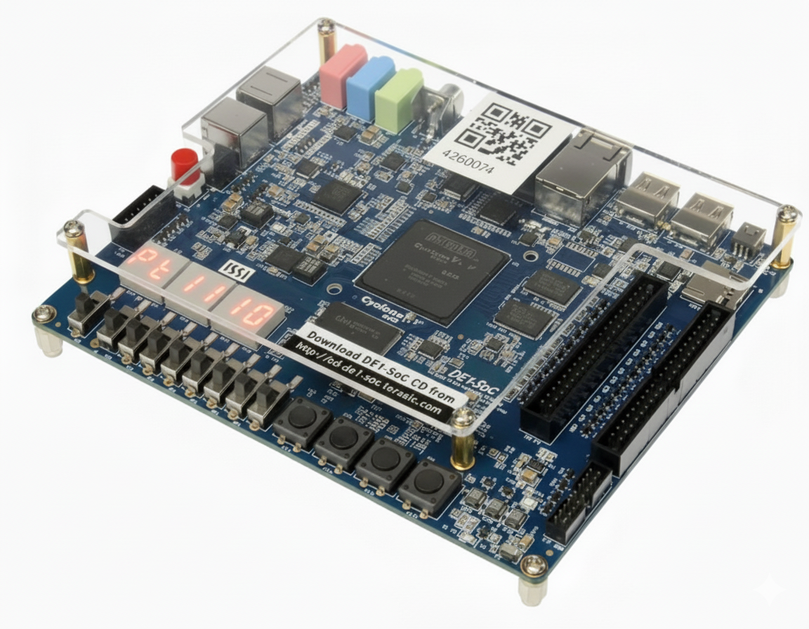
Craps game running on FPGA with 7-segment display output
Module Architecture
The design is structured as six distinct Verilog modules, each responsible for a specific function, connected together through a top-level file:
- DiceGame.v top-level module that instantiates and connects all components
- FSM.v finite state machine controller managing four game states: init, reroll, win, and lose
- TestLogic.v combinational logic that evaluates each roll against Craps rules and determines the outcome
- counters.v 16-bit Linear Feedback Shift Register (LFSR) for pseudo-random dice generation, producing values 16 for each die independently
- Adder.v adds the two 3-bit die values into a 4-bit sum for evaluation
- bcd7seg.v BCD to 7-segment display decoder driving the physical display output
RTL data path and FSM state diagram
Simulation and Verification
Each module was individually simulated in ModelSim before integration. Testbenches were written to cover all Craps rule outcomes: immediate wins (7, 11), immediate losses (2, 3, 12), point establishment, and subsequent point resolution in both the win and lose directions.
The complete integrated design was verified end-to-end in simulation before being synthesized and programmed onto the FPGA.
ModelSim simulation waveforms showing game state transitions
FPGA Integration
After simulation, the design was synthesized in Quartus Prime and programmed onto an Intel FPGA development board. A push button serves as the roll trigger, with the LFSR continuously running so that the exact clock cycle at which the button is pressed determines the dice outcome producing effectively random results from the player's perspective.
The two 7-segment displays show the current value of each die, and dedicated LEDs light green on a win and red on a loss.
7-segment display output and win/loss LED indicators on the FPGA board